C - AVR - Simple PORTB, DDRB, PINB explanation
Categories:
Demystifying AVR I/O: Understanding PORTB, DDRB, and PINB
Unlock the secrets of AVR microcontroller I/O registers. This guide provides a clear explanation of PORTB, DDRB, and PINB for effective hardware control.
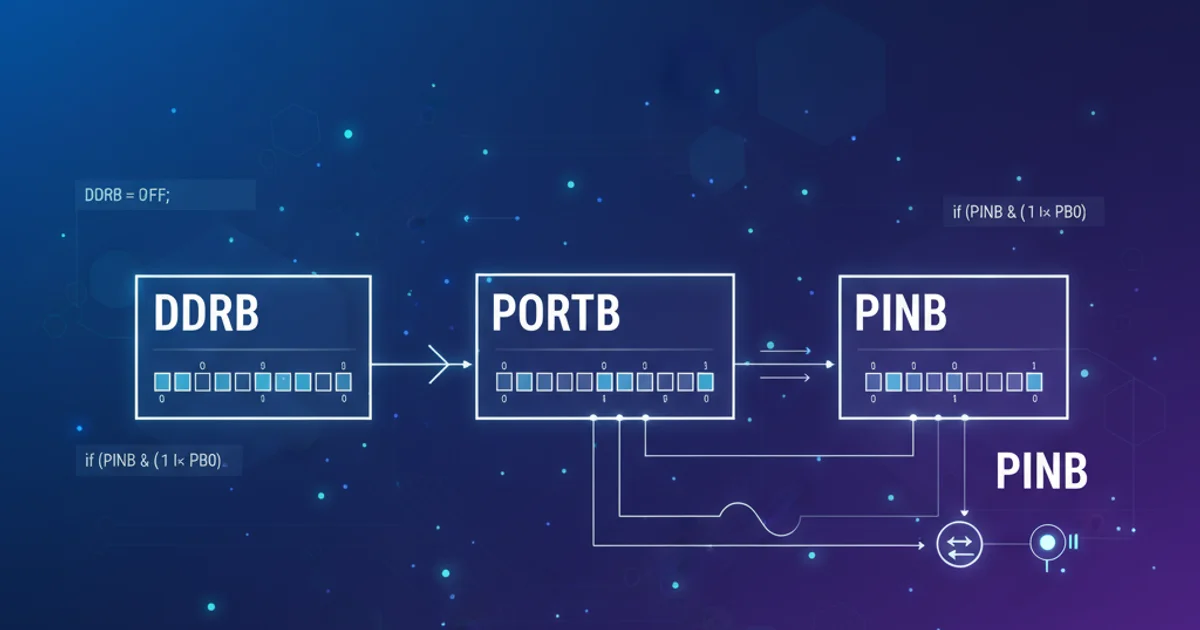
When working with AVR microcontrollers, understanding how to control the General Purpose Input/Output (GPIO) pins is fundamental. The ATmega series, like many other microcontrollers, uses special function registers to manage these pins. This article will focus on the three primary registers associated with a specific port, using PORTB as our example: DDRB, PORTB, and PINB. Grasping their individual roles and how they interact is crucial for configuring pins as inputs or outputs, reading sensor data, and driving external components.
The Data Direction Register (DDRx)
The Data Direction Register (DDRx, where 'x' is the port letter, e.g., DDRB for Port B) is responsible for setting the direction of each pin on a given port. Each bit in DDRx corresponds to a specific pin on that port. A '1' written to a bit in DDRx configures the corresponding pin as an output, while a '0' configures it as an input.
// Configure PB0 as output, PB1 as input
DDRB = (1 << PB0) | (0 << PB1);

// A more common way to set PB0 as output and clear PB1 as input
DDRB |= (1 << PB0); // Set PB0 as output
DDRB &= ~(1 << PB1); // Clear PB1 as input

// Set all pins on PORTB as outputs
DDRB = 0xFF;

// Set all pins on PORTB as inputs
DDRB = 0x00;
Examples of configuring pin directions using DDRB
(1 << PBx) for clarity and portability, as PBx refers to the bit number for pin x on Port B, which is defined in the AVR header files.The Port Register (PORTx)
The Port Register (PORTx) has a dual function depending on whether the pin is configured as an output or an input by DDRx.
When a pin is configured as an output (DDRx bit is '1'): Writing a '1' to the corresponding bit in PORTx will set the pin to a high logic level (VCC), and writing a '0' will set it to a low logic level (GND). This is how you control the voltage on an output pin.
When a pin is configured as an input (DDRx bit is '0'): Writing a '1' to the corresponding bit in PORTx will enable the internal pull-up resistor for that pin. Writing a '0' will disable the pull-up resistor. Pull-up resistors are essential for input pins that might otherwise float, leading to unpredictable readings.
// Assuming PB0 is configured as output (DDRB |= (1 << PB0);)
PORTB |= (1 << PB0);  // Set PB0 high
PORTB &= ~(1 << PB0); // Set PB0 low

// Assuming PB1 is configured as input (DDRB &= ~(1 << PB1);)
PORTB |= (1 << PB1);  // Enable pull-up resistor for PB1
PORTB &= ~(1 << PB1); // Disable pull-up resistor for PB1
Examples of using PORTB for output control and pull-up resistor management
The Pin Input Register (PINx)
The Pin Input Register (PINx) is used exclusively for reading the logical state of the physical pin. When you read from PINx, you are reading the actual voltage level present on the pin, regardless of whether it's configured as an input or an output. However, it's primarily used to read the state of pins configured as inputs.
If a pin is configured as an input, reading its corresponding bit in PINx will tell you if the external signal is high ('1') or low ('0'). If a pin is configured as an output, reading PINx will reflect the voltage level that the microcontroller is currently driving on that pin.
// Assuming PB1 is configured as input (DDRB &= ~(1 << PB1);)

if (PINB & (1 << PB1)) {
    // PB1 is currently high
} else {
    // PB1 is currently low
}

// Read the entire PORTB input state
unsigned char portb_state = PINB;
Examples of reading pin states using PINB
flowchart LR
    subgraph AVR Microcontroller
        DDRB[DDRB Register] -->|Configures direction| PORTB_Logic
        PORTB[PORTB Register] -->|Controls output/pull-up| PORTB_Logic
        PINB[PINB Register] <--|Reads physical state| PORTB_Logic
    end

    PORTB_Logic(Port B Pin Logic) <--> Physical_Pin(Physical Pin PBx)

    DDRB -- '1' --> Output_Mode(Output Mode)
    DDRB -- '0' --> Input_Mode(Input Mode)

    Output_Mode -->|PORTB '1'| High_Output(High Output)
    Output_Mode -->|PORTB '0'| Low_Output(Low Output)

    Input_Mode -->|PORTB '1'| Pull_Up_Enabled(Pull-up Enabled)
    Input_Mode -->|PORTB '0'| Pull_Up_Disabled(Pull-up Disabled)

    Physical_Pin -- 'High' -->|Read PINB| Logic_High_Read(1)
    Physical_Pin -- 'Low' -->|Read PINB| Logic_Low_Read(0)
Interaction of DDRB, PORTB, and PINB with a physical pin