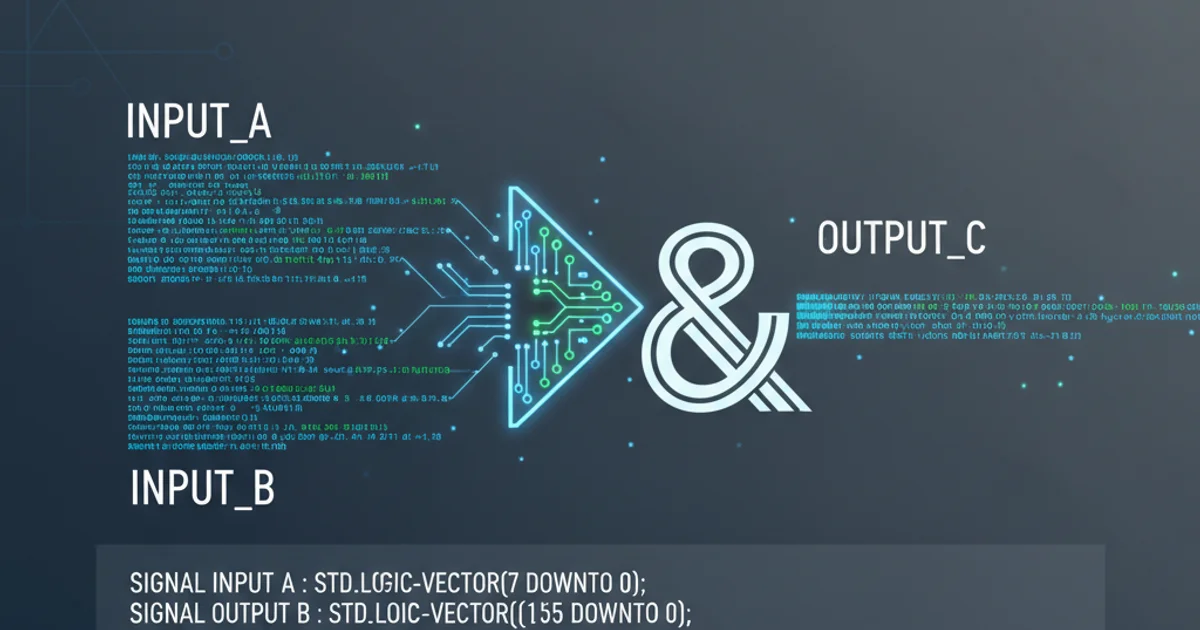
Concatenating bits in VHDL
Categories:
Mastering Bit Concatenation in VHDL for Digital Design

Learn the essential techniques for concatenating bits and bit vectors in VHDL, a fundamental operation for building complex digital circuits. This guide covers basic syntax, common pitfalls, and best practices.
In VHDL, concatenating bits and bit vectors is a common operation used to combine smaller data units into larger ones. This is crucial for tasks like forming wider data buses, constructing control signals, or manipulating individual bits within a larger word. Understanding how to correctly use the concatenation operator (&) is fundamental for any VHDL designer.
The Concatenation Operator (&)
VHDL uses the ampersand symbol (&) as its concatenation operator. This operator allows you to join two or more bit or bit vector operands into a single, larger bit vector. The order of operands matters, as the left-most operand will form the most significant part of the resulting vector, and the right-most operand will form the least significant part.
LIBRARY ieee;
USE ieee.std_logic_1164.all;

ENTITY Concatenation_Example IS
    PORT (
        bit_a   : IN  STD_LOGIC;
        bit_b   : IN  STD_LOGIC;
        vector_c: IN  STD_LOGIC_VECTOR(2 DOWNTO 0);
        result  : OUT STD_LOGIC_VECTOR(4 DOWNTO 0)
    );
END ENTITY Concatenation_Example;

ARCHITECTURE Behavioral OF Concatenation_Example IS
BEGIN
    -- Concatenating individual bits and a vector
    result <= bit_a & bit_b & vector_c;

    -- Example with literal bits
    -- another_result <= '1' & '0' & vector_c;

    -- Example with multiple vectors
    -- vector_d <= vector_c & vector_e;

END ARCHITECTURE Behavioral;
Basic VHDL code demonstrating the use of the concatenation operator (&).
& operator works with STD_LOGIC and STD_LOGIC_VECTOR types. Ensure all operands are compatible or explicitly cast them if necessary.Understanding Operand Order and Resulting Width
When concatenating, the resulting bit vector's width is the sum of the widths of all its operands. The order in which you list the operands directly determines their position in the final vector. The first operand becomes the most significant part, and subsequent operands fill in towards the least significant part. This is crucial for maintaining correct data alignment.
flowchart LR
    subgraph Inputs
        A[bit_a: STD_LOGIC] --> Concat
        B[bit_b: STD_LOGIC] --> Concat
        C[vector_c: STD_LOGIC_VECTOR(2 DOWNTO 0)] --> Concat
    end

    Concat["bit_a & bit_b & vector_c"] --> Result[result: STD_LOGIC_VECTOR(4 DOWNTO 0)]

    style A fill:#f9f,stroke:#333,stroke-width:2px
    style B fill:#f9f,stroke:#333,stroke-width:2px
    style C fill:#f9f,stroke:#333,stroke-width:2px
    style Result fill:#bbf,stroke:#333,stroke-width:2px
Flowchart illustrating the concatenation process and resulting vector formation.
Consider the example above: bit_a (1 bit), bit_b (1 bit), and vector_c (3 bits) are concatenated. The result will be a 5-bit vector. If bit_a is '1', bit_b is '0', and vector_c is "101", then result will be "10101". The bit_a occupies the most significant bit (MSB), followed by bit_b, and then vector_c forms the least significant bits (LSBs).
Common Use Cases and Best Practices
Concatenation is widely used in VHDL for various purposes. Here are some common scenarios and best practices:
- Forming Data Buses: Combining smaller data segments into a wider bus.
- Creating Control Words: Assembling individual control flags into a single register.
- Padding/Extending Vectors: Adding leading or trailing zeros/ones to match required widths.
- Bit Manipulation: Extracting and reassembling parts of a vector.
Best Practices:
- Clarity: Use clear variable names to indicate the purpose of each concatenated part.
- Explicit Widths: Always define the exact width of your resulting vectors to avoid synthesis issues.
- Type Consistency: Ensure all operands are of compatible types (
STD_LOGICorSTD_LOGIC_VECTOR). If mixing, ensure proper casting or useSTD_LOGIC_VECTORfor all parts where possible.
LIBRARY ieee;
USE ieee.std_logic_1164.all;

ENTITY Advanced_Concatenation IS
    PORT (
        data_in_low : IN  STD_LOGIC_VECTOR(7 DOWNTO 0);  -- 8-bit low part
        data_in_high: IN  STD_LOGIC_VECTOR(7 DOWNTO 0); -- 8-bit high part
        enable_flag : IN  STD_LOGIC;
        status_bits : IN  STD_LOGIC_VECTOR(1 DOWNTO 0);
        full_data   : OUT STD_LOGIC_VECTOR(15 DOWNTO 0); -- 16-bit data bus
        control_word: OUT STD_LOGIC_VECTOR(3 DOWNTO 0)  -- 4-bit control word
    );
END ENTITY Advanced_Concatenation;

ARCHITECTURE Behavioral OF Advanced_Concatenation IS
BEGIN
    -- Forming a 16-bit data bus from two 8-bit parts
    -- data_in_high forms the MSB, data_in_low forms the LSB
    full_data <= data_in_high & data_in_low;

    -- Creating a 4-bit control word
    -- '0' is a padding bit, enable_flag is a control bit, status_bits are status flags
    control_word <= '0' & enable_flag & status_bits;

END ARCHITECTURE Behavioral;
Advanced VHDL concatenation examples for forming data buses and control words.